Quadro elettrico per controllo riscaldatore 19 MW


Delivered a control panel for a fluid heather project. The system is composed of four units for managing a total power of 19 MW. There is a central CPU connected through the network to the relative peripherical modules.


Sistema a barre in alluminio


The control panel is connected, through the Profinet protocol, to the customer DCS system, which centrally manages all the plant processes.

The fluid temperature is controlled by a hybrid system that works in steps, by combining the continuous adjustment of SCR with the on/off one of the contactors. In this way, the ratio cost-performance is optimised.


Quadro di distribuzione da 3 MW

We have just delivered an electrical cabinet for distribution with a power of 3 MW. The cabinet will feed a system for tests in a wind tunnel.

Quadro di distribuzione da 3 MW

The cabinet uses three SCR (silicon controlled rectifier) of 1 MW each. For further details regarding SCR please have a look to this post: Electrical cabinet for power distribution at 1.6 MW.

Quadro di distribuzione da 3 MW

Quadro elettrico di potenza da 800 kW

The order for an electrical cabinet with a power of 800 kW has just been concluded. The cabinet will feed a heating system for a water tank in order to avoid that during winter the water could freeze.

This system has four separate feedings, but it has an only integrated controller for thermoregulation. This regulation is manageable both locally and remotely by a DCS system.

CIE 45mo anniversario

To our father.

This year our company reaches 45 years of activity into the industrial automation sector. We would like to remember the main stages of this growth path that has brought us to the level of experience and maturity that distinguishes us today.

1975

CIE was founded by Rodolfo Cesare with its headquarters in Monguzzo (CO). The first steps were taken in the installations of both civil and industrial electrical systems. The main sectors are the installations for surface and thermal treatments.

The document of the registration at the chamber of commerce

The document of the registration at the chamber of commerce

1976

Shortly after its beginnings, the production of explosion-proof systems began.

An Alitalia order of an explosion-proof system for the maintenance of aicrafts.

An Alitalia order of an explosion-proof system for the maintenance of aicrafts.

1982

CIE moves to its new headquarters in Merone (CO).

1985

The sectors covered include the chemical industry as well.

Switchboard inner part of a power centre supplied to a chemical plant.

Switchboard inner part of a power centre supplied to a chemical plant.

1995

With the purpose of focusing on the industrial sector, the civil systems are abandoned.

The first pages of a wiring diagram for a washing tunnel.

The first pages of a wiring diagram for a washing tunnel.

1998

To complete the know-how in industrial automation, PLC programming is introduced.

2007

The company is in continuous expansion and needs a roomier location, a building in a new industrial complex in Monguzzo (CO) is chosen.

2008

The continuous technical progression brings to the design and realisation of plants dedicated to research and development.

2010

The expansion towards an environmental sustainability sector begins, which is the one of water treatment and purification.

2015

Besides electrical installations and PLC programming, an innovative system for supervision and remote control is developed: the IPS Cloud.

2016

The geographical expansion brings to the UL certification for exporting to the American market as well.


Since it was born, CIE never stopped growing, not only in size but, above all, regarding its competences. The development of know-how has always been our priority, and we feed it with the desire to analyse and use new technologies. In this sector, keep up with the times is essential and we put all our efforts to ensure that this remains true for the years to come.


Andrea and Gabriele Cesare

Busbar System

When the design of a low-voltage electrical panel begins, among other things, we face the decision about how to make the power distribution. We have two ways: either using wires or opting for a busbar system. Let’s analyse which are the aspects to be considered in order to make the best decision.

What standards say

The first thing to do is to look at standards. In this case, the standard is EN 61439-1, which regulates the low-voltage switchgear and controlgear assemblies. According to the standard, there are no situations in which we are forced to use one solution rather than the other, but there are thresholds above which it is necessary to verify the short-circuit resistance. In these cases, having busbar systems makes things much easier. The standard requires the distribution system to be tested directly or to be verified by comparison with a reference design. In this case, the use of a busbar system is advantageous, given that normally the manufacturers have already made a series of tests for the various configurations. The comparison can be made either with a checklist contained in the standard or through calculations. In any case, the system must have the same or better characteristics than the tested reference. And also for this verification, busbar manufacturers normally come to our aid.

The limits provided by the standard, under which it is not necessary to verify the short circuit, are the following:

  • The rated short-time withstand current (Icw) or the rated conditional short-circuit current (Icc) not exceeding 10 kA r.m.s.
  • If a current-limiting device is present and the limited peak current (Ipk) does not exceed 17 kA at the maximum allowable prospective short-circuit current.
  • For auxiliary circuits only, if connected to transformers whose rated power does not exceed 10 kVA for a rated secondary voltage of not less than 110 V, or 1.6 kVA for a rated secondary voltage less than 110 V, and whose short-circuit impedance is not less than 4 %.

A study on short-circuit currents

Let’s better understand what the various short-circuit currents are.

Andamento corrente di cortocircuito

The trend of the short-circuit current over time. During the first fractions of a second, a peak (Ipk) appears, which then goes to fade, stabilizing at a certain value (Icp). The time required to reach this last current value is of the order of magnitude of 1s. In reality, the trend of the current is not symmetrical as schematized in the graph, but shifted to one side, becoming symmetrical only when Icp is reached.

Peak current

Ipk – in red on the graph. It is the absolute maximum value that the short-circuit current reaches at the beginning of the fault. It is possible to limit this current with limiting devices, such as fuses and switches. In this way, the peak current can be lowered below the threshold to avoid short-circuit verification.

Rated conditional short-circuit current

Icc – in yellow in the graph. It is the r.m.s. value of current (simplifying a lot, it is the current that gives the same effect of an equivalent DC supply) of short-circuit which the electrical panel must withstand until the protection device trips.

Rated short-time current

Icw – in green on the graph. It is the r.m.s. current relative to the short-circuit test for a defined time, without the tripping of protections. It means that no element of the electrical panel must be damaged by the passage of this current for a defined time. Normally 1s is used, but it may vary. It is also possible to assign different Icws for different times to the same panel.

prospective short-circuit current

Icp – in blue on the graph. It is the value the short-circuit current would tend to if it were not interrupted by the protection devices. We can see it as the steady-state short-circuit current after the initial amplified phase is damped. In practice, this current is never reached, as the protections trip to stop the fault.

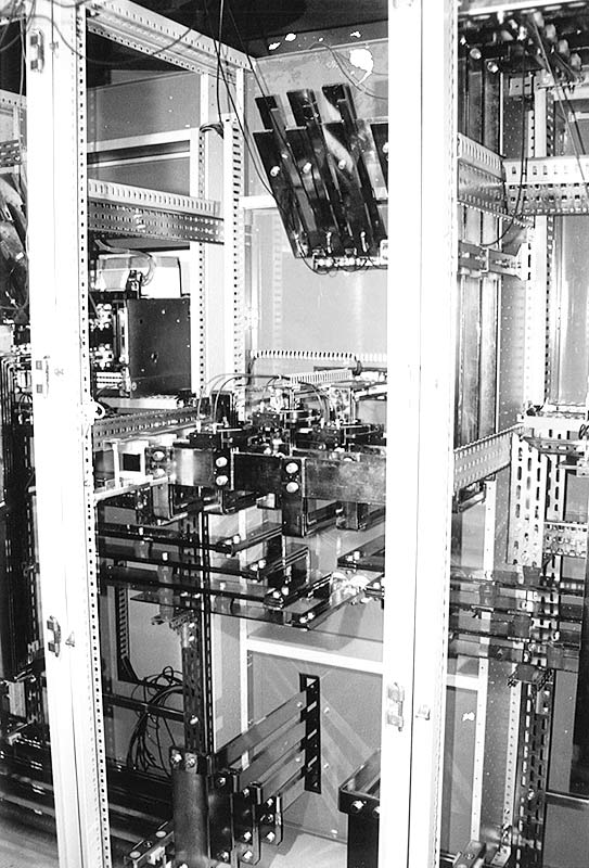
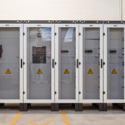
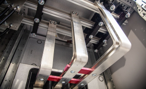
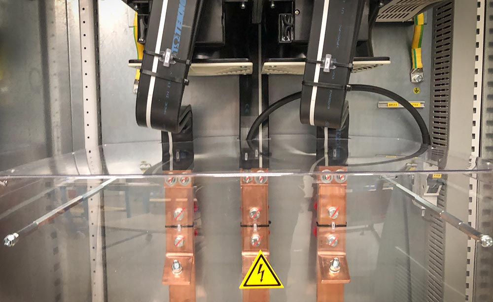
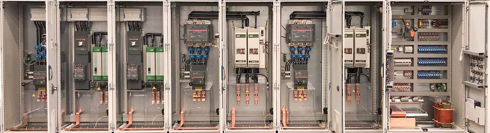
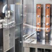
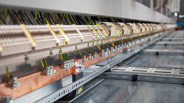
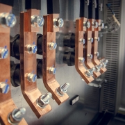
The advantages of using a busbar system

As we have seen above, if we exceed the thresholds for which the standard requires verification, the first advantage lies in the ready-made tests that the busbar system supplier can give us, certifying our system. But is it convenient to use busbar systems even when we are below these thresholds? The answer is yes, because, as we will see shortly, the benefits are numerous.

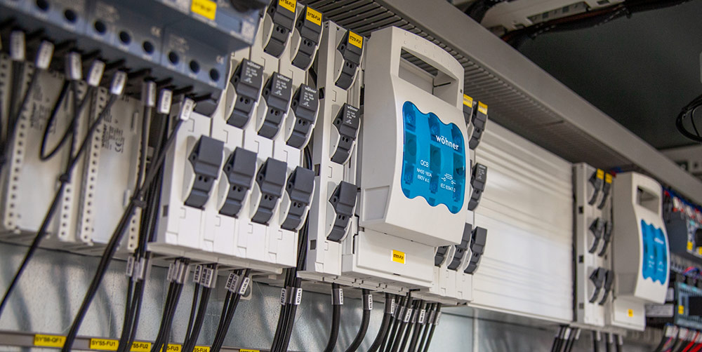
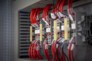
  • Better short-circuit resistance. Regardless of whether we are asked for a short circuit test or not, a busbar system guarantees a higher short circuit resistance than wires and certainly also a more predictable behavior.
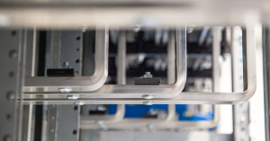
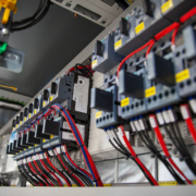
  • Reduction of manpower hours. A wired system requires a longer work compared to the assembly of a busbar system, which leads to a reduction in labour costs.
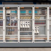
  • Small panel size. This aspect has a double advantage: a reduction in the panel costs and an advantage for the customer who will have a smaller occupied volume.
  • Ease of expansion. The busbar systems allow easier and faster connections in the event of future additions, plus the facilitation given by the left free space.
  • Less risk of overheating on the connections. The accessories are connected with spring systems, therefore they are not subject to loosening over time. This also eliminates the need for periodic checks of hardware tightening.
  • Tidier aesthetics. Certainly, the aesthetics of the panel also benefit, showing a more orderly and clean appearance.

If we now look at what we have on the other plate of the scale, we find a higher cost of the material compared to a wired system. But, considering all we have on the pros plate, the scale continues to lean towards the busbar systems. Our suggestion, when making these evaluations, is to look at all the aspects and think about what will happen in the future, not stopping at the comparison of the mere cost of the material, which is only a point on a much longer list.

Almost completed the project for automation of a plastic recycling plant, which includes 15 electrical cabinets along the entire line. The system consists of a structured network with a central PLC connected to each cabinet. This CPU is the central brain that controls all the sensors positioned along the line.

On a plant of this size, supervision is certainly an element that cannot be missing. A dedicated computer will be installed to manage all the signals and allow them to be monitored in real time.

We recently concluded the Oil & Gas project regarding the control of a 1.6 MW heater. In order to obtain the requested adjustment, the system uses thyristors (SCR).

We would like to spend a few words to explain what a thyristor (or SCR – Silicon Controlled Rectifier) is and what advantages it can bring. It is a component similar as a diode and it varies from the latter for the presence of a third terminal called “gate”, which has a signal applied for activating the diode conductivity. It is made of a quadruple layer of semiconductors p-n-p-n and is connected as a transistor couple in accordance to diagram in the figure.

This component, coupled with a PID controller (proportional-integral-derivative), reaches precision levels considerably higher compared to an electromechanic system based on contactors. Furthermore, it guarantees a higher response speed. it is also important to underline that a thyristor not only adjusts the power with a series of switch on and off, but it acts on the wave, cutting it at a determined threshold.

CERTIFICATE OF COMPLIANCE

Cie srl in order to meet the customers’ requests for the American market has been certified according to the UL standards for the execution of electrical cabinets ( UL 508A Standard – Industrial Control Panels ).


Monguzzo, 01.05.2017

The company CIE S.n.c. Of F.lli Cesare, by a notarial act, has been transformed to LIMITED RESPONSIBILITY COMPANY, also transferred its registered office from Longone al Segrino Via Monticelli no. 4, to Monguzzo Via Valassina n. 18 A1 and changed the capital stock to € 50,000 fully paid-up., however, remained unchanged the VAT number, the tax code and the bank data.

From 01/05/2017 all correspondence and documents should be headed to:


CIE S.R.L.

Via Valassina n. 18 A1

22040 – MONGUZZO (CO)

P.I./C.F .: 02907720136

Automation for water treatment plant for Volkswagen MAN Truck – Munich